Round accessory table
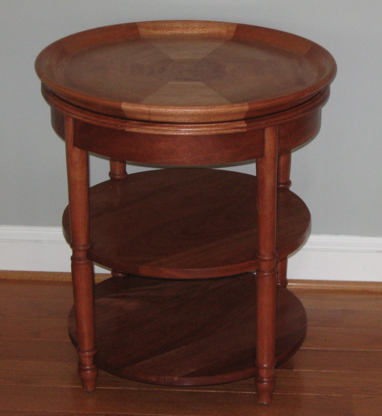
This simple round accessory table required the use of every major pieces of equipment in the shop. The project incorporated the diverse skills of geometric layout, steam bending, glue lamination and lathe turning. Ironically, the complex skills to make the parts ended up being screwed together – not a lot of fancy joinery required to complete the round accessory table.
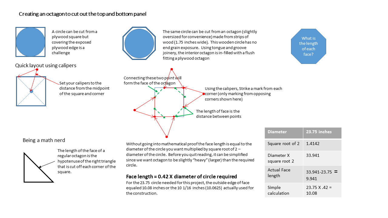
The round accessory table construction started with making the segmented octagonal top which is then cut into a circle and profiled on a lathe. The segments were cut from a glued up blanks of African Mahogany. To create a lipped edge, a four feet long piece of 3 inches wide of 8/4 Mahogany is glued to 10.5 inches wide of 4/4 (requires two blanks). Using the mathematical relationship between the diameter of a circle and the side of an octagon (Lay out an octagon -use back arrow to return) I could cut 4 – 10.5 inches wedges -from each blank with minimum wastage. Using the “thick lip” saved material and time spent on the lathe creating the lipped table top when compared to hogging out the center of a top made from 8/4 material alone.
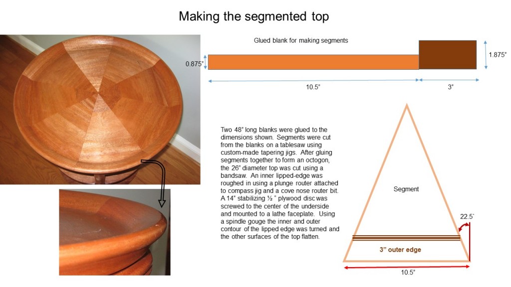
The real challenge to making a round accessory table is turning a 24 inches diameter table-top blank on the lathe. My JET lathe has outboard turning capabilities so that is not the issue – the minimum speed of 500 rpm is the issue. For a 24 inch diameter circle the effective surface speed at the outer lip is 35 miles per hour. A chisel catch gives new meaning to a brown shorts moment. Much like a wheel on your car, the slightest imbalance causes major vibrations. To ensure a solid attachment, a 12 inches diameter plywood circle is fastened onto the bottom side of the top via one screw into each of the eight segments forming the top. A six inch face plate is then center on this disc and attached with all 8 available screw locations. These screw penetrates through the plywood disc and at least 1/2 inch into the top. The “wobble” coming from the top surface being not parallel to the faceplate is minimized by loosening a screw and adding sheets of aluminum foil between the faceplate and plywood disc. (trial and error approach until the wobble is the best as can be expected). Any wobble because you did not center the turning blank or failed to cut a circle from the octagon is a risk management decision about correcting the error before proceeding.
After sharpening the spindle gouge, start forming the outside edge of the table top. Before moving to the internal lip edge, I used a plunge router, bull nose bit and compass jig to rough in the inner lip-top interface. A spindle gouge and bowl gouge created the edge sweep. The 80-grit gouge (sandpaper) was used to smooth the top surface (speed and grain orientation caused the spindle gouge to leave shallow ridges along the surface) before sanding down to 320 grit and applying a stain.
The legs were turned from 1 7/8 inches square pieces 24 3/4 inches long. Each spindle is first rounded to a 1 5/8 inches cylinder along the entire length. Next the foot/bead is formed three inches from the bottom end. A second bead is located four inches from the bottom end. The area between the beads is reduced to 1 3/8 inches diameter. Starting at the top end the process is repeated at a distance of 12 1/2 and 13 1/2 inches. The spindle is then tapered.
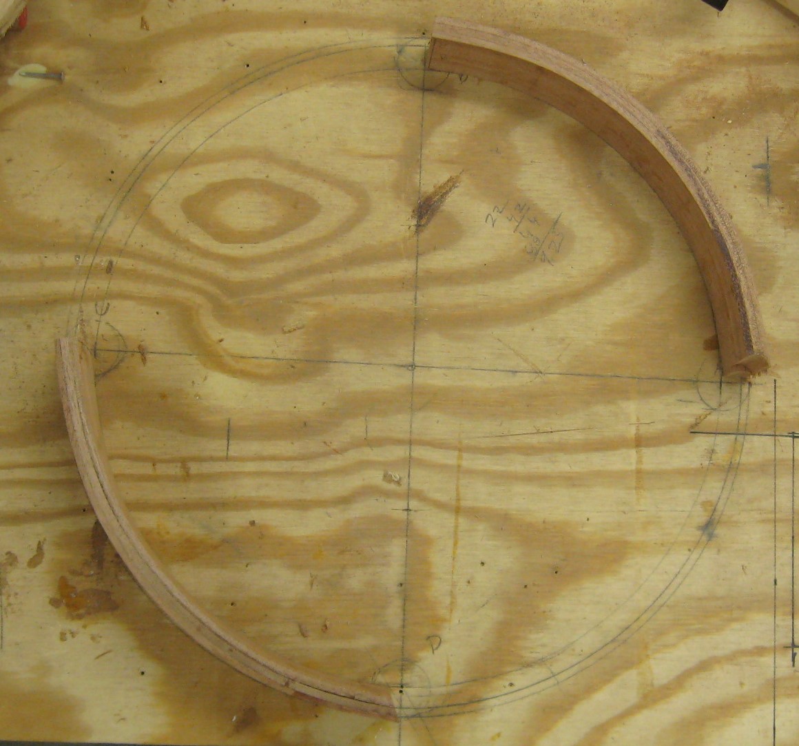
The supporting table base’s final dimensions uses the finished top’s bottom diameter as the starting point. This diameter is drawn on the workbench surface and two perpendicular lines are drawn from the origin to intersect the circumference. Reduce the compass setting by 3/4″ to draw a circle with a diameter 1 1/2 inches less than the original circle. The gap between these two circles represents the location of the 3/4 inch thick apron. Each intersection of the perpendicular axis and the small inner circle represents the origin of a 1 5/8 ” circle that locates the each of the four support legs. Using measurements from the full scale drawing an octagon that will yield a circle with a diameter of the smaller circle is built. The leg locations are determined and a 1 5/8 ” holes are drilled with an forstner bit before the circle is cut from the octagon shape. This “internal ring” sets the location of all components used to create the apron/leg table support.
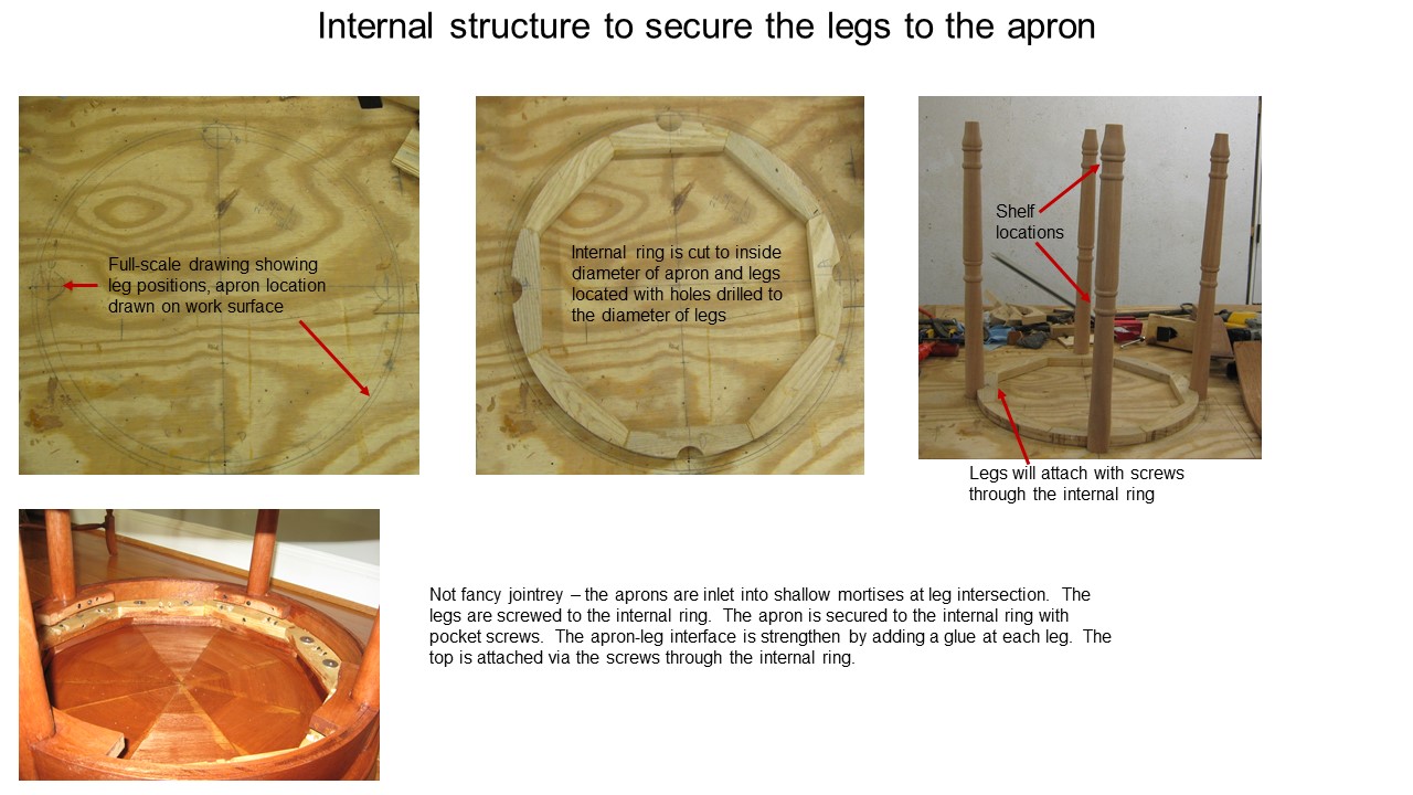
Simple construction incorporates elements of accurate layout and precision cutting.
The apron rails have a 22 inches radius (radius of the internal circle from the full scale drawing). To make the 4 apron pieces a combination of steam bending and glue lamination was used. I had 1/4″ thick pieces of African Mahogany left over from the African Mahogany library project. Test piece showed that this 3 inches wide,kiln-dryed material would conform to the radius if it was steamed, bent to a form and allowed to dry. For once, the left over material from another project provided a surplus of 3 extra pieces instead of needing to source 1 or 2 pieces to complete the task.
Three pieces were “ganged” together, steamed and bent to conform to a 22″ bending template. Technically, each piece has a slightly different radius. After drying at least 24 hours, the pieces are glue laminated using PPR glue and a clamping jig cut to mimic the final desired apron radius.
Rough cut apron blanks to length
After squaring to a 2 3/4 ” width dimension, the pieces are rough cut at locations taken from the full scale drawing. The internal ring now takes command of the process.
Locate the four legs on the internal ring. Label parts so they can be returned to same location during the “fitting and assemble” phases. One end of each apron is cut to an angle similar to the one formed at the intersection of the perpendicular line and the inner circle. This angle does not need to be a perfect mating but angle consistency and location is important. A cutting template made from the internal ring’s cutting scraps was attached so the angle was formed with the power miter saw setting at 90 degrees. This template design ensured a repetitive accurate cut. The leg is held in its assigned location on the internal ring and the angle cut apron is snugged against the internal ring and leg intersection. The apron profile is traced on the leg using a utility knife. The knife is then used to deepen the profile lines to about 1/8″ deep. The waste material is removed with a chisel. This shallow dado (mortise) entraps the end of the apron. Repeat the process on the remaining legs.
You have now reached the point of no-return in the sense that up to now any minor mistake could be trimmed off and corrected. Attach one leg to the internal ring with a screw through the internal ring. Entrap the apron in the dado and hold it tight against the internal ring. Mark the intersection point of the next leg and a point about 1/8″ beyond that point (cut off mark). Cut the apron to length at the cut off mark. Remove the screw holding the first leg and remove the leg from its position on the internal ring. Use the apron to mark the intersection on the second leg and follow the same procedure used previously to create the second shallow dado to receive the apron. Return and re-secure the first leg to its position with the screw. The receiving leg dado’s depth and apron’s length are fitted via trial and error until the second leg will fits into its location on the internal ring. Secure the second leg with a screw and start repeating the process for the remaining legs. Do not be surprised if you have to repeat the process “around the circle” to fine the tune the assembly.
Disassemble the dry fit pieces from the internal ring. In the areas between the leg location on the internal ring, add three pocketholes to each segment. Now start assembling the table by attaching a leg to the internal ring with a screw. Entrap an apron segment by securing the second leg to its location. Repeat until all legs and apron segments are in place. Use a strap clamp to tighten the structure and start screwing the apron segments in place using the pocketholes to locate screws. The apron entrapment is completed with Glue blocks screwed at the lower apron-leg interface.
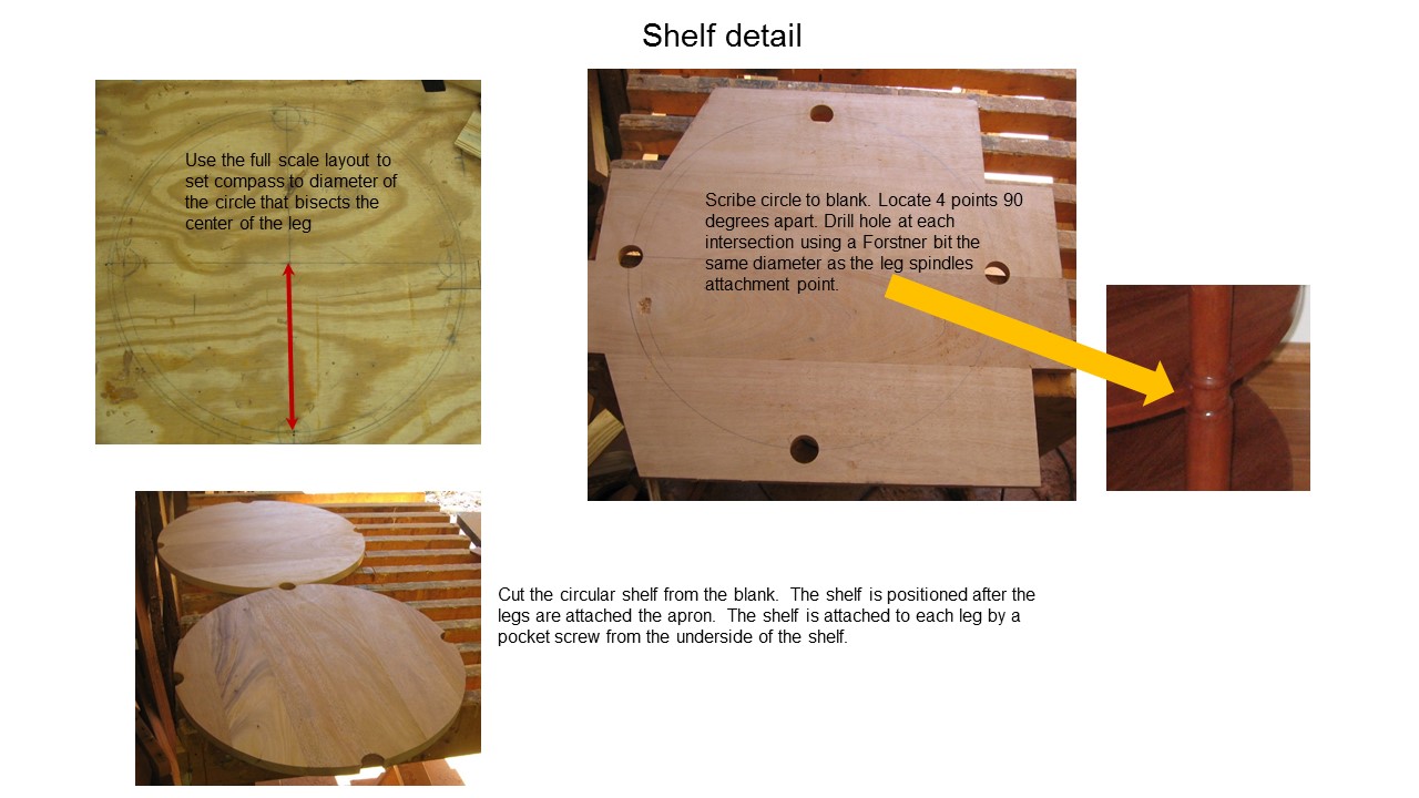
Method for attaching shelves to the table legs