Cypress bed – Voice of Customer
Voice of Customer Designs a bed
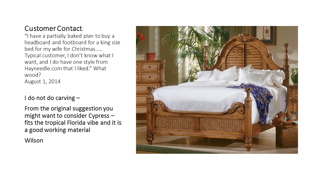
Work colleague makes initial contact with an idea.
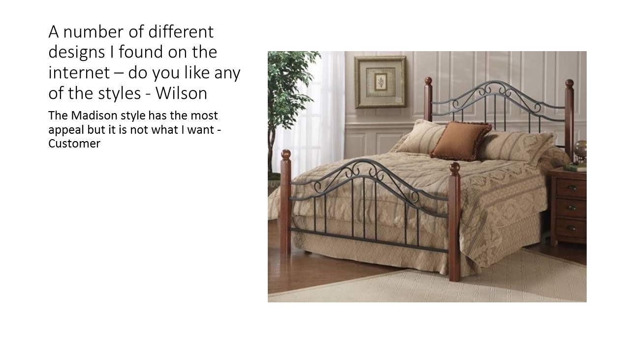
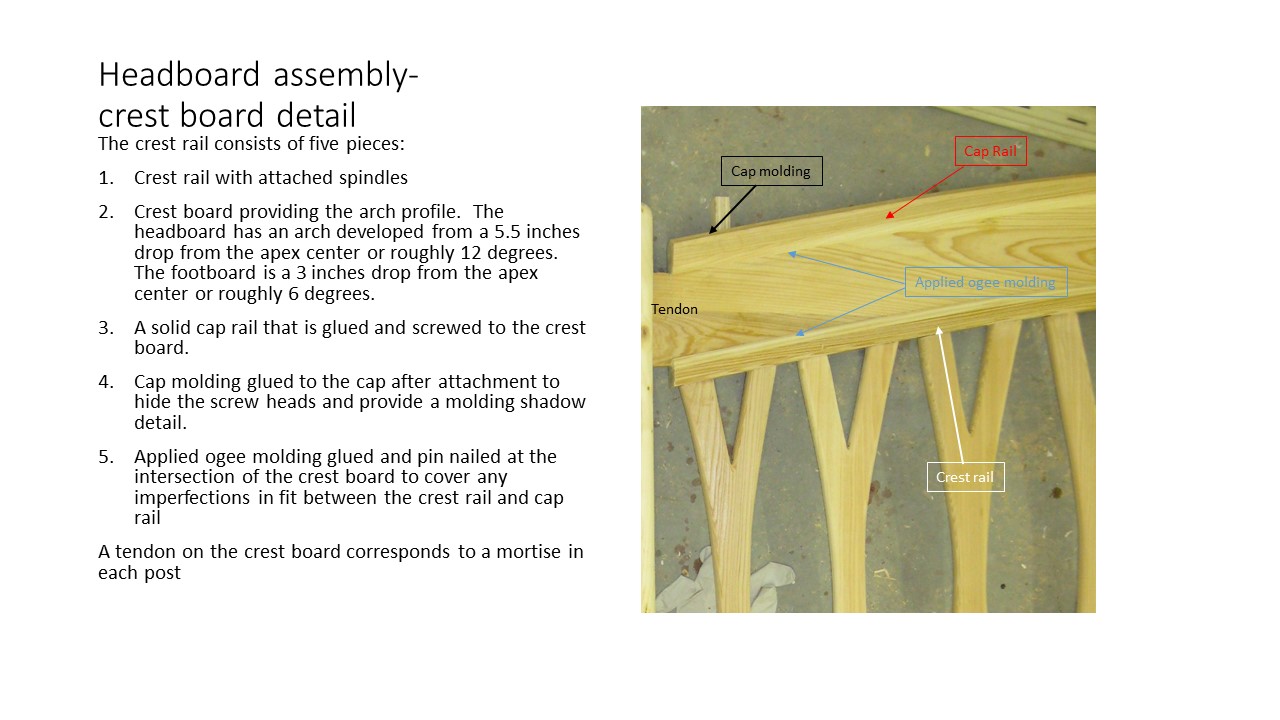
The web provided a diverse design selections
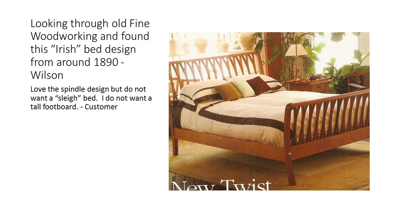
The design gains traction when a style is chosen
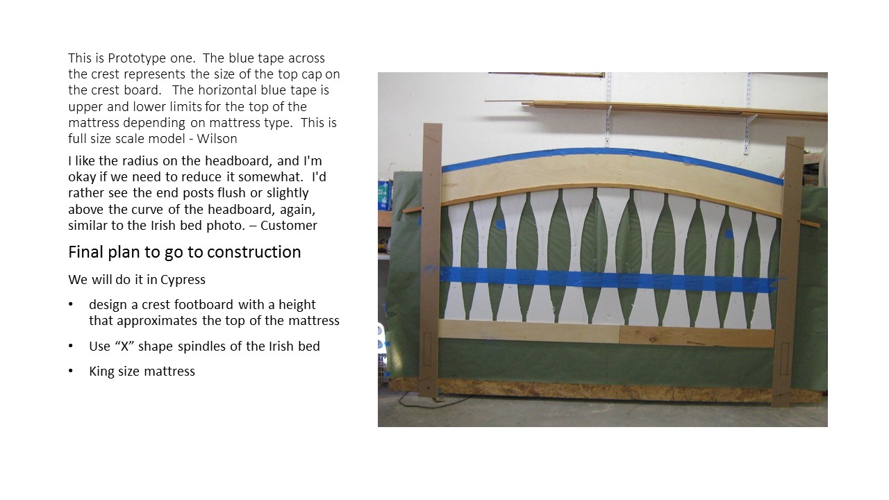
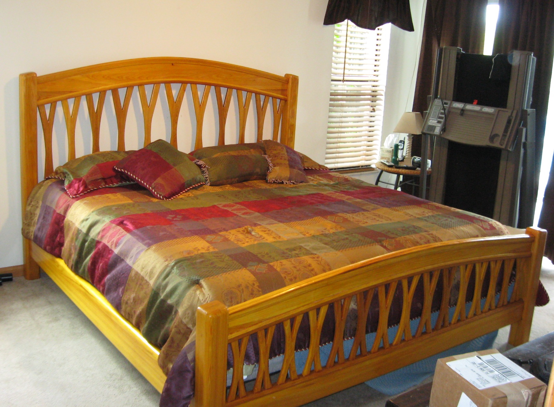
Full size mock up is used to finalize the design
Voice of Customer becomes a bed
The oils in cypress’ heartwood resist decay from moisture exposure and impart golden brown to light blonde color. Moisture resistance makes Cypress the natural choice for exterior exposures and it is not generally thought of as a source for interior applications. I have found over several projects that the golden brown to blonde color and prominent growth rings which create natural geometric pattern whenever exposed along any rounded edge provide a palette of choices to make a unique piece of furniture. The easily to mill and shape characteristic of Cypress comes from what I call good grain integrity – meaning it resists splitting and splintering when cutting or using mechanical fasteners and is dimensionally stable if it is properly seasoned.
Working with Cypress
Being a coniferous wood, Cypress does not lend itself to steam bending. One reason for making the full scale model shown above was to verify that I could spring a piece of 3/4 inch Cypress to the arch I wanted for the crestboard – 6 inches of drop over a 37 inches distant – without splitting or cracking. From that point the model became the design board to work out the spindle design, spacing and most importantly the development of a full size template of the crestboard arch.
I got lucky and found a source of 8/4 select grade Cypress from Transit Lumber in Richmond, VA. So on a hot September morning I took the 100 mile trip for material acquisition. The 100 mile trip was like making a 100 year trip back in time – Transit Lumber was pleasant reminder of a slower life and a friendly customer orientated business I remember from my youth. The last time I bought Cypress in 2003 it was a reasonably price alternative to clear white pine – well that has changed. Cypress is now priced in neighborhood of the Africa Mahogany that I used to complete the library project but at least the select grade means you get quality for the dollar.
Bed construction
After preparing the rough lumber’s surface, the 8/4 Cypress resulted in a 1 7/8 thick boards. The future bed post were ripped into 3 3/4 wide blanks. Using the jointer, a 1/16 inch was removed from a single face of each blank to ensure a flat gluing surface. The remaining 8/4 Cypress broads were planed to 1 3/4 inches thick and the 7 inch side rails and 4 1/2 inch headboard and footboard bottom rails were cut to width.
The construction process begins with bed post. The bed post is the point of intersection for the removable side rails and permanently joined headboard rail and footboard rail. The side rails are secured with a drawbolt/dowel system while the mortise and tendon joints are used for the permanent joints. The drawbolt location is not in the center of the rail so you need to offset the hole toward what will become the inside of the bed. The trick is keeping track so you do not end up with two right hand or two left headboard or footboard posts.
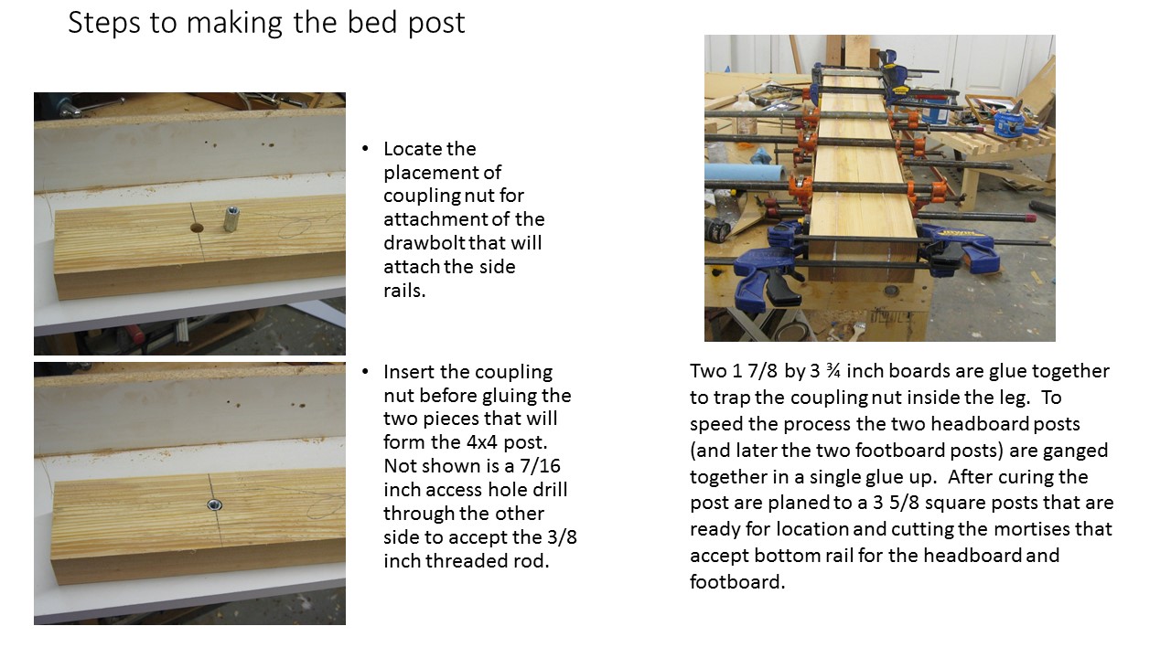
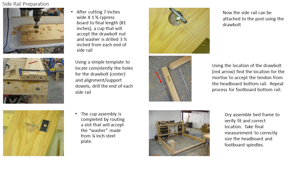
The drawbolts are 3/8 inch threaded rod cut to the needed length. One end threads through an 7/16 access hole into the coupling nuts that are encapsulated in the bedpost and the other end passes through a 7/16 inch hole drilled into the end of the side rail. It emerges into 1 inch deep 1 1/2 inch diameter cup where the tightening nut and heavy duty steel washer secures the side rail to the bedpost. The side rail access hole for the drawbolt is centered at a location 3 1/2 inches from the edge and 5/8 inch from the face (cup side). Two 1/2 inch holes centered 1 3/4 from the edge and 7/8 inch from the face accepts 1/2 inch dowels that strengthen the joint and prevent twisting as the drawbolt is tighten.
Construction of side rails
The drawbolts are used to locate the mortises for headboard and footboard bottom rail. The tendons on these rails are relieved 3/4 inch from a single face (rabbet joint) instead of relieving both faces as customary. The non-cut face is considered the “public” face and no crack will appear if future joint movement occurs. Once located the 1 1/8 inch mortises are cut by removing the bulk of material with a 1 inch fostner bit and trimmed to the layout lines with chisels. The first dry assembly of the frame verifies the locations developed for the side rails and bottom rails results in a square frame that sits level on the floor.
Headboard design
The customer’s desire for the X-shape spindles shown in the Fine Woodworking article’s sleigh bed was not a “simple copy the plan” design because there is no spindle curvature required to create the sleigh bed design. In the sleigh bed, all X-spindles were the same width and length. A crest shape headboard shortens the spindle length as you progress from the center (30 inches) toward the bedpost (24.5 inches). During the development of the prototype spindles with the same width created a “heavy” look and the resulting optical illusion made the spindles appear wider at the bedpost than those toward the center. The illusion dampen the visual appeal of the crest shape by making the curvature look flatter. To change the visual shape the width of the spindles were varied. The center spindle was 7 inches wide and each spindle’s width decreased in half inch increment progression until the spindles adjacent to the bed post were 4.5 inches wide. Another deviation was the addition of bottom rail cap that allowed the spindles attachment via screws instead of dowel pinning and precision drilling of the spindles, crest rail and bottom rail.
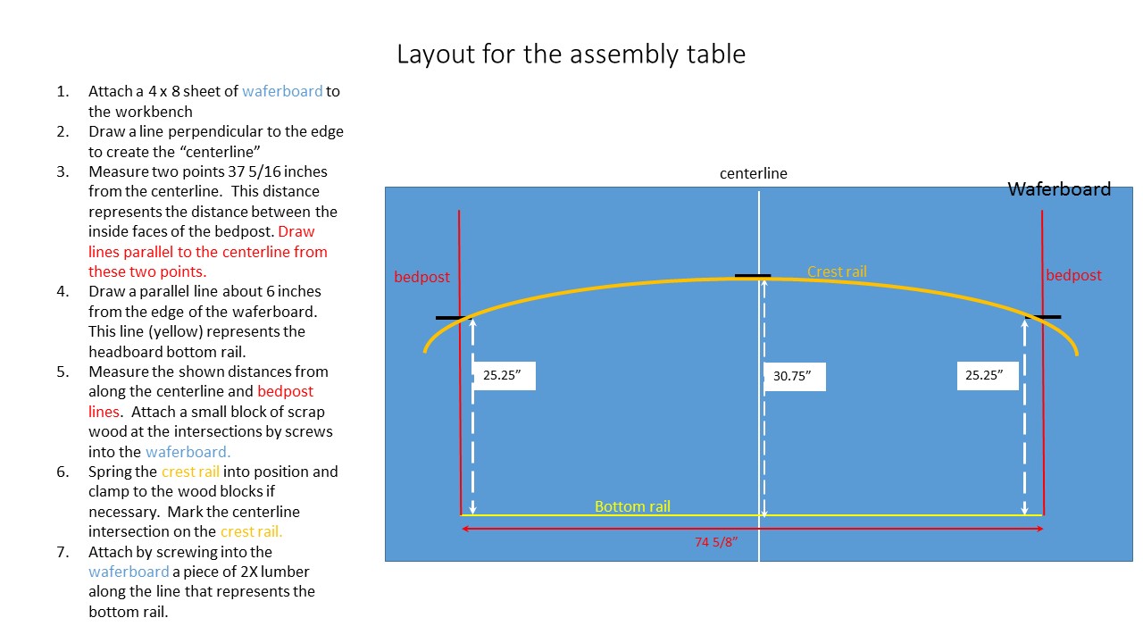
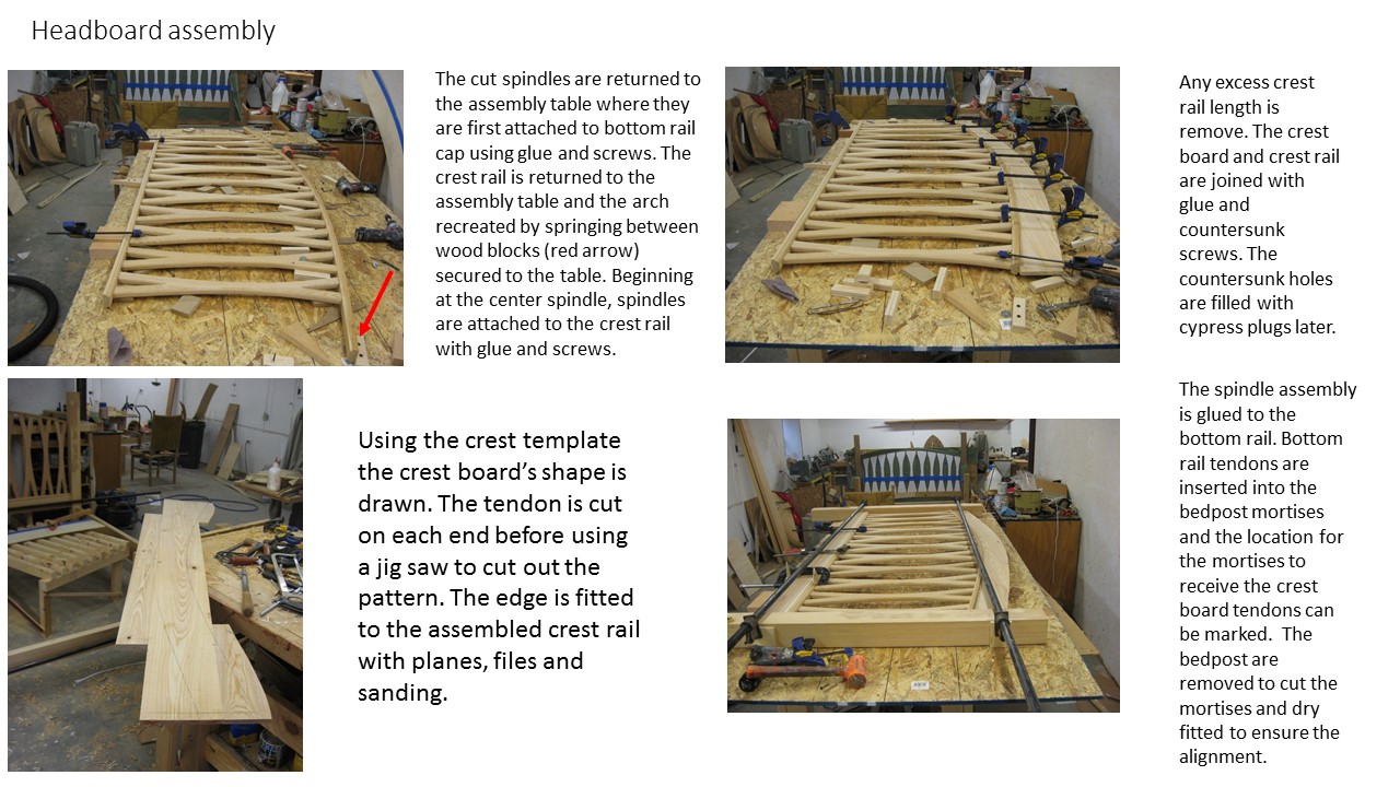
The scale model for the prototype was converted into an assembly table to speed the determination of each spindle’s exact length and intersection angle at the crest rail. By springing the 3/4 thick crest rail board to the assembly table , the headboard is constructed to the actual arch that forms instead conforming the crest rail to a drawn arch. The natural arch is reproducible during the several drying fitting assemble/disassemble steps that follow. After clamping the 3/4 inch bottom rail cap to the assembly table, Cypress boards cut to the width of the corresponding spindles are arranged with equal spacing between each board along the bottom rail cap. For this bed the spacing worked out to 1 1/8 inches. Some scrap 3/4 in plywood was cut in a 1 1/8 strip to serve as spacer blocks.
Before laying out the spindle shape, a correct length for the spindle’s location in relation to the arched crest rail is needed. The process starts with the 7 inches wide spindle that is bisected by the centerline on the assembly table. This spindle is screwed to the centerline in an area that will later be removed during the shaping of the spindle. The length is marked 1/2 inch longer than the intersection with the crest rail. A spacer block is place at the bottom rail and crest rail intersection and the distant between the two rails plus 1/2 of inch is transferred to the blank that will become the next spindle. After cutting to length, the blank is returned to the assemble table location and the procedure repeated until all the blanks have been marked. Note at this point, only center spindle is secured in place and the other boards are located with the spacer blocks relative to the center spindle.
With the spindle shape complete, it is time to return to the assembly table. The 1 1/2 inches wide x 84 inches long crest rail is still sprung into the arch form on the assembly table. Using the 1/4 plywood strip from the prototype carefully scribe transfer the crest rail’s arch shape to the plywood. It is important that you mark the center line location on this new arch plywood template. Cut the template arch with a jig saw and carefully fit the template to the crest rail using files, block planes and sandpaper. Each time you test the fit make sure you align the template with the center line.
Remove the bottom rail cap (1 3/4 x 74 5/8) and crest rail from the assembly table. Cut a 1/4 cove recess on the crest rail and 7/32 ogee detail on the two edges of the face that the spindles will intersect. Return on the bottom rail cap to the assembly table and clamp into position after aligning that the center line mark and the center line on the assembly table. The center of the spindles (thickness plane) will align with the center of the bottom rail cap if you place a 1/2 inch plywood spacer between the spindle and assembly table. With “feet” of the center spindle tightly held against the bottom rail cap, center the “V” intersection of the “arm and legs” over the center line. Using fend washers as “clamps” and 2 inches round head screws placed in the void area near the “V”, secure the spindle to the assembly table. Repeat the steps using 1 1/8 inch spacer blocks at intersection between the “arms and legs”. Mark the approximate center of each leg on the bottom rail cap. Use the crest board template to mark the length of the spindle arms.
click on image to enlarge
click to enlarge image
Click to enlarge image
Foot board design
We now turn our attention to the footboard. To achieve an height at the approximate top of the mattress, the top of the footboard crest needs to be about 28 inches above the floor level. This is roughly 1/2 the height of the headboard so the footboard design feature is reducing the height of the X-spindles by roughly 1/2 (12 1/2 inches max height), the crestboard dimension 1/2 (3 inches) and the curvature by 1/2 ( 3 inches drop over 37 inches). The assembly board is reconfigured to these new specifications and the layout of the spindles begins. The first visual design change was to reduce the maximum spindle width from 7 to 5 1/2 inches for the center spindle. The shorter spindle height means the progressive incremental decrease in width is not a paramount factor in maintaining the visual balance so the incremental decrease was 5.5, 5, 4.5, 4, 4, 4, 3.75, 3.5 (center to post). It now takes 15 spindles instead of 11 to cover the distance from post to post.
click on image to enlarge
Final thoughts
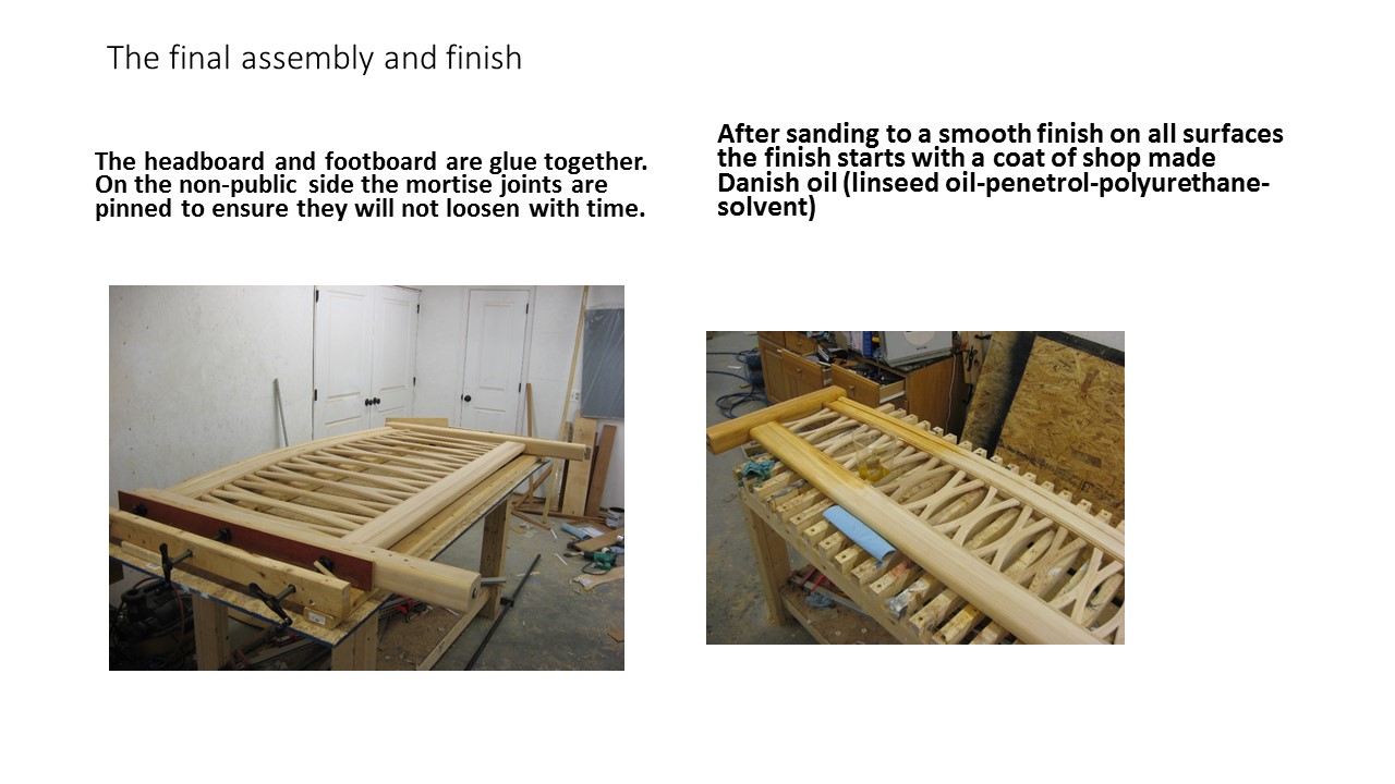
This project demonstrates that furniture building does not require rigid following of measured plans. The bed essentially designed itself after the prototype established the voice of customer by setting the starting form and established the location of the rail and post intersection. The ability to cut and dry assemble the components parts means the components were fitted after their creation instead of created to fit a predetermined location. This flexibility made the crest rail spring arch possible.